Principles of Operation
While using Pulse Width Modulation (PWM), you can adjust the control signal (TTL) to an RF-excited CO2 laser over a wide range of frequencies. The laser gas will not respond to the signal beyond its own limit of frequency response. To an electrical engineer, this is akin to an RC low-pass filter, where the input is a square wave (control), and the output is DC with some ripple (laser power).
You can take advantage of this low-pass feature to adjust the power level without the unwanted pulsing behavior, by using very high-frequency PWM, as illustrated in the scope traces below. We call this PWM-CW.
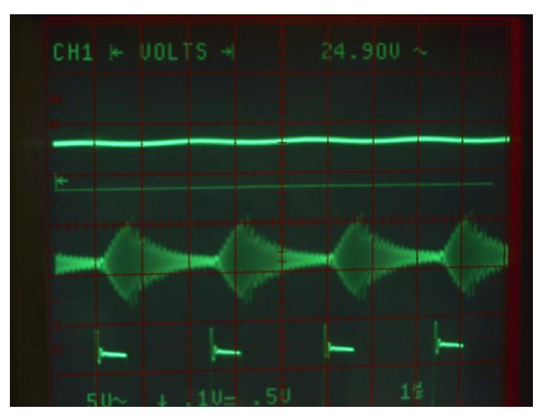
Figure 1. Modulation at 400 kHz with 25% duty cycle. The top trace is laser power measured by a room-temperature MgCdTe detector. Zero power reference is the dash line. The second trace is the RF waveform. The third trace (partial) is the TTL gate signal.
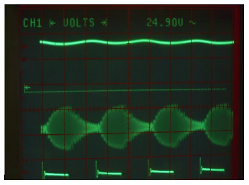
Figure 2. Modulation at 400 kHz with 50% duty cycle. The top trace is laser power measured by a room-temperature MgCdTe detector. Zero power reference is the dash line. The second trace is the RF waveform. The third trace (partial) is the TTL gate signal.
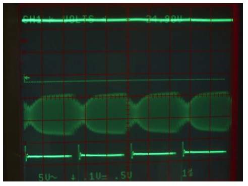
Figure 3. Modulation at 400 kHz with 91% duty cycle. The top trace is laser power measured by a room-temperature MgCdTe detector. Zero power reference is the dash line. The second trace is the RF waveform. Third trace (partial) is the TTL gate signal.
Cautionary Notes : Access Laser products can be readily modulated electronically, at up to 100 kHz. Special adjustments can be made to achieve as high as 400 kHz for some models. If this is desirable, please contact our factory. Do not modulate a standard laser beyond 100 kHz. If your application requires a narrow band optical signal, do not use PWM-CW. A typical stabilized Access Laser product has a line width of less than 100 kHz running true CW, but if it is driven by PWM-CW the line width can be broadened.
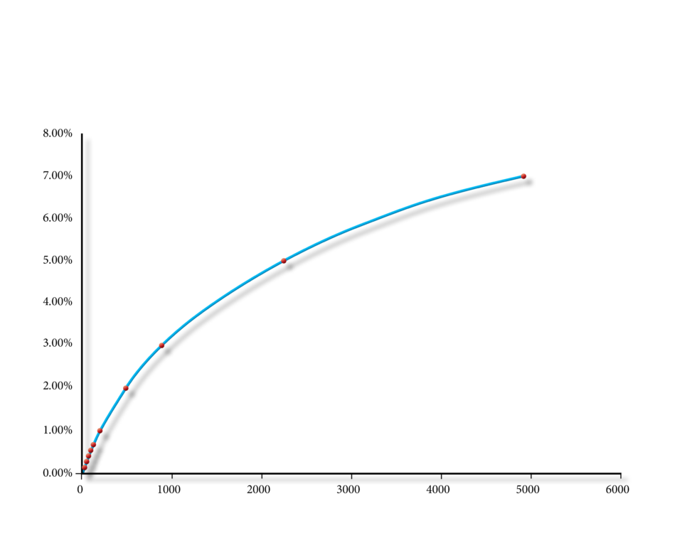
Figure 4. Typically, the higher the frequency of the PWM the higher the Threshold Duty Cycle (TDC) for a laser. The TDC is the duty cycle where lasing action start to occur. Below TDC, there is no lasing. Following is an example of TDC vs. frequency.
At around the threshold the laser power can be very unstable.
Pulse Height Adjustment:
It is also possible to treat this high-frequency signal as the carrier and modulate it with a low-frequency signal to achieve a pulse waveform that can be adjusted both on its amplitude (by high frequency) and on pulse length (low frequency). This effect is illustrated in the following examples.
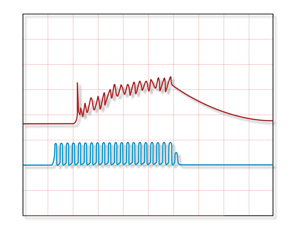
Figure 5. Low duty cycle of 30%, in high frequency can be seen in the blue trace. The yellow trace is the laser pulse.
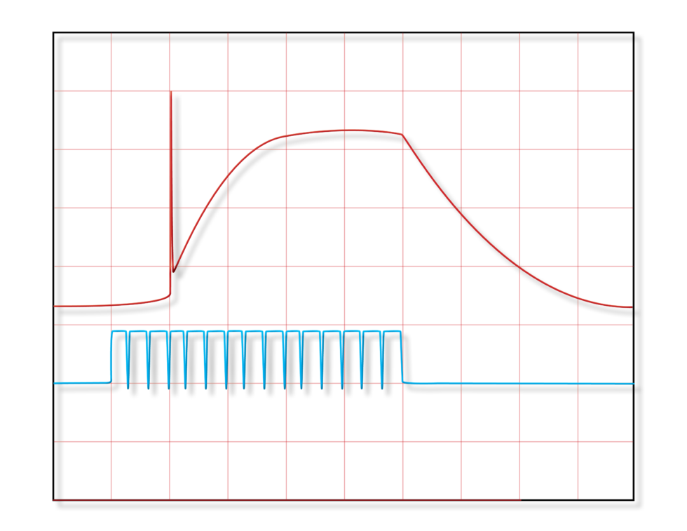
Fig 6. Higher duty cycle of 90%, resulting in higher peak power in the laser pulse.