In the past driven by the semiconductor and telecommunications industries, it is today’s advances in computational materials science that require flexible manufacturing technologies for the synthesis of tomorrow’s crystalline materials such as ceramics, piezoelectrics, superconductors etc.
However, only a few years later, in 1955, Henry Theuerer developed the first floating zone technique. A vertically arranged germanium rod was pulled through a localized melt zone created by an RF heating coil. The absence of a crucible allowed the growth higher purity crystals, but of limited diameter (< 200 mm). By the 1970s, the telecommunications industry was increasingly interested in growing single crystal oxides of small-diameter and high-purity due to their advantageous material properties for fiber optical applications.3 The floating zone technique was the preferred choice but could not be applied due to inefficient RF heating of the oxides. A solution to this problem was presented in 1972 by John Haggerty, who used CO2 laser radiation to create the floating zone in a fiber drawing process. Further improvements by Martin Fejer and Robert Feigelson in 1980 helped to establish the so-called Laser-Heated Pedestal Growth (LHPG), as shown in Figure 1.4
In recent years, advances in computational materials science have led to high demand for methods to exploit synthesis of new materials. The 2019 Materials by Design Roadmap reports that for the first time, the number of theoretically predicted materials exceeds the number of experimentally known entries in crystallographic databases. Thus, a shared interest by many scientists includes flexible manufacturing methods to test these newly predicted materials.5
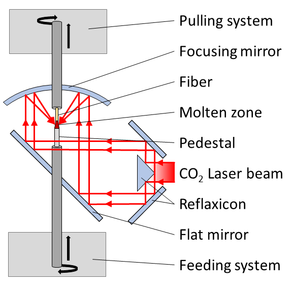
Application: LHPG is such a method used in industry and material research, notably for high melting point materials, because of its flexible and cost-effective fabrication of single crystal fibers. LHPG uses focused CO2 laser radiation to create a floating melt zone. For this purpose, the laser beam is guided into a closed chamber where it hits a reflaxicon which converts the laser beam to a hollow cylinder shape. The beam is then guided to a parabolic mirror which focuses the radiation over the pedestal source.4
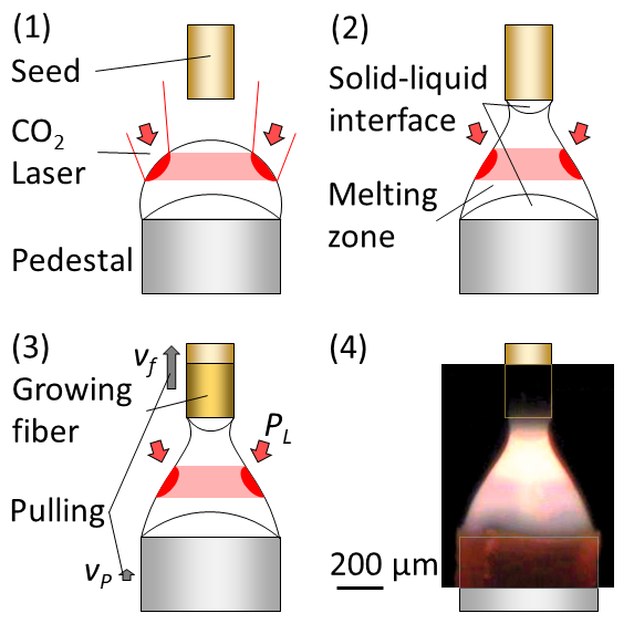
The fiber drawing takes place in three steps, as shown in Figure 2. First, the focused laser radiation creates a small melt zone on top of the pedestal. Second, a seed crystal is introduced into the melt zone, creating solid-liquid interfaces at the pedestal and seed. And third, the melt zone and solidification at the seed are fed by the continuous pulling of the fiber. Under these con-trolled conditions, it is energetically favorable to maintain the seed’s microstructure during solidification, which enables the continuous growth of the single crystal. Stable thermodynamic conditions, and thus a stable CO2 laser source, are essential for success. In practice, however, small thermal fluctuations lead to a variation of the fiber diameter. This can be overcome by using a stabilized laser source, such as Access Laser’s AL50ST, and by monitoring the melt zone (Figure 2.4). Precise control of the pulling rate vf, vP, and the laser power PL can minimize the diameter variations to less than 1%.4 The laser power required to keep the melt zone stable varies from 10 to 200 W depending on the material, diameter, pulling rate etc. Single crystal fibers with diameters from 25 µm to 1 mm have been realized.
Bottom line: Using CO2 laser radiation as a heating source has two major advantages over other methods. First, the wavelength of 10.6 µm is well absorbed by many relevant oxides. And second, laser radiation can be easily focused, resulting in high local temperatures and gradients. The high temperature gradients enable 60 times faster growth — mm/min instead of mm/h — and the processing of materials with very high melting points. This includes materials of great interest to material science and industry such as silica, sapphire, YAG, superconductors, functional ceramics, ferro-, opto-, and piezoelectric materials, and eutectic compounds.4 The great flexibility in producing single crystal fibers of high melting point materials at low cost makes LHPG a powerful tool.
1. Pajaczkowska, A. (2001): Prof. Dr. Jan Czochralski – An Inventor. Newsletter of the German Association for Crystal Growth (73), 30. ISSN 2193-3758
2. Evers, J. et al (2003): Czochralski’s Creative Mistake: A Milestone on the Way to the Gigabit Era. Angewandte Chemie International Edition, 42(46), 5684-5698. DOI: 10.1002/anie.200300587
3. Rudolph, P. (2014): Handbook of crystal growth: Bulk crystal growth. Elsevier. ISBN 9780444633033.
4. Andreeta, M.R. et al (2010): Laser-heated pedestal Growth of oxide Fibers. In Springer Handbook of Crystal Growth. 10.1007/978-3-540-74761-1_13.
5. Alberi, K. et al (2019): The 2019 materials by design roadmap. Journal of Physics D: Applied Physics 52.1 (2018): 013001.
___________________________________________
Author: Sandro Eckert
Sales & Application Engineer
Email: sales@accesslaser.com
Phone: +1 (425) 582 – 8674